# Shrimping it
The arduino platform is a great platform to work with, it is easy to code for and has a nice learning curve. However, after you have finished playing with and tweaking your circuit you are left with a fairly bulky and costly product. This is fine most of the time, when you are just playing and experimenting, but can quickly become a pain when you have multiple more permanent projects. So what can you do about it? Well, this is where a shrimp comes into play. A shrimp is basically a bare bones arduino, normally constructed on a breadboard or strip board, fully compatible with the arduino sdk, and only costs about a 10th of the price (< £6).
# The Components
The shrimp does not require many components, most of which can be bought very cheaply and are readily available.
- ATMEGA328P-PU*
- Breadboard/Stripboard
- USB to Serial converter**
- 16MHz crystal oscillator
- 2x 18-22pF ceramic capacitor
- 4x ~100nF ceramic capacitor
- 1x 10uF electrolitic capacitor
- 1x 1k-10k resistor (exact value does not matter)
- 1x LED
- 1x resistor to match the LED***
- 1x Switch (Optional)
- Some wire
* The ATMEGA328P is one of the most expensive part of the shrimp, typically you can get them for £2-£5 depending on the quantity you want and if they are preprogrammed with the Arduino bootloader. This guide assumes you have a chip with the bootloader preprogrammed, if you get a chip without the bootloader you will need to flash the bootloader onto it which can be done with another Arduino/Shrimp or an AVR programmer. Flashing the bootloader is not covered in this article. Also watch out for the ATMEGA328 chips, they are almost identical to the ATMEGA328P chips except they do not have a low power mode and will not work out of the box with the Arduino tool kits. It is fairly easy to get them to work, but doing so is outside the scope of this article.
** You should be able to use any FTDI based board for this, however these tend to be fairly expensive (~£10), you can also use a UART based chip which you can find on ebay quite cheap (~£2) however not all of these boards break out the required pins. Make sure you get one that has the following pins broken out: DTR TX RX +5V/+3V Ground (the order is not important). The UART chips can require you to solder on an extra pin to expose the DTR line, but this is not hard to do.
*** Make sure you get a resistor value to match the LED you are buying. See this for more information, typically the values are around 100-330Ohms, to low and you risk burning out the LED, to high the LED wont be as bright so it is better to overshoot the value slightly.
# Building The Shrimp
First of all we start with the ATMEGA328P chip, this is the heart of the Arduino Uno, where your sketches will run and where all input and outputs will be connected and driven/read. The chip has a maximum of 23 I/O pins, although you cannot use three of these pins in the Arduino Uno for general I/O, they are reserved for the external crystal (XTAL1-2 in the diagram) and the reset pin. This leaves 19 digital I/O pin, six of which can be used for analogue input (ADC0-5), and another 6 for PWM output. The chip also has two serial pins, two that can be used for I2C communication and three for SPI communication allowing the chip to talk to a wide range of devices and other chips. Below is a complete breakout of the ATMEGA328P chip:
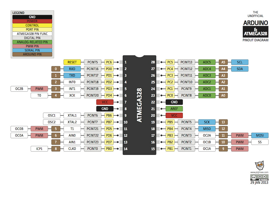
Image from http://www.pighixxx.com/
The chip has a small notch at the top, this indicates which side pin 1 is located on, you may also notice a small dot next to pin 1 (not visible on the diagram above). Use these markings to orientate the chip the correct way around.
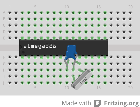
The next step is the crystal, this is responsible for keeping timing for the ATMEGA328 and controls the speed at which the chip runs at. The ATMEGA328 has an internal crystal capable at running at 1MHz or 8MHz and is capable of running up to 20MHz on an external crystal. The Arduino Uno uses a 16MHz crystal, so that is what we will be using. You can use a 20MHz crystal, or even the internal one however that requires modifying the boards.txt which is beyond the scope of this article. The crystal is connected to XTAL1 (pin 9) and XTAL2 (pin 10), it is not polarized so does not matter which way you connect it. Each of the crystal pins are connected to ground through a couple of 22pF capacitors and help to stabilize the crystals signal.
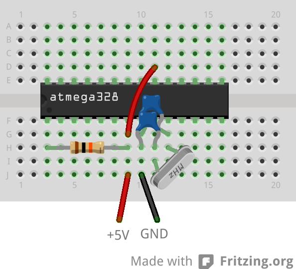
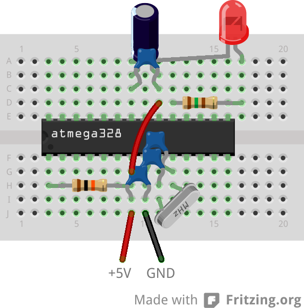
The ATMEGA328 has two ground pins and two VCC pins. The ground pins (pins 8 and 22) are connected internally, so you only need to wire one up. The VCC pins however are not connected internally, pin 7 is used to power the micro-controller and can be powered by 3.3-5V. The ATMEGA328 can be run at lower voltages, but only with a slower crystal. Pin 20 is used to power the analogue to digital converter and is only needed if you want to use the analogue pins if you do then just connect it to the voltage you will be using for your analogue circuits, if it is the same one that powers the digital one so you can just short it to pin 7. Lastly, we should connect the reset pin to VCC, this keeps the reset pin high and stops the chip from randomly resetting. If you wish to reset the chip, just short this pin to ground.
And that is it! You have a fully functional shrimp, however it won't do much without some inputs or output so lets connect an LED to see it do something. There are many ways to do this, for example you can use any of the I/O pins, however the Arduino Uno uses pin 19 (digital pin 13) for their led and is what the blink sketch uses by default so we will be doing the same.
Simply connect the LED through a resistor to ground or VCC, you can use the ATMEGA328 as both a current source or sink so it does not matter if you connect it to VCC or ground (as long as you connect the LED the right way around, with the flat side to ground). The only difference is that if you connect it to VCC then you have to reverse the logic in your program as setting digital pin 13 to HIGH will turn off the led and vice versa. We have chosen to connect it to ground so we don't have to worry about reversing the logic.
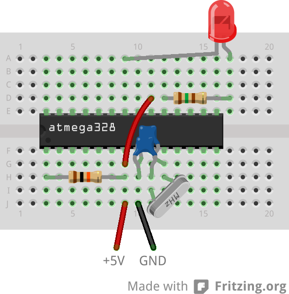
If your ATMEGA328 has the blink sketch uploaded to it then you can power it up and the LED will start blinking at you.
However, if you use this in other circuits you may find the chip randomly reset every now and then, especially when connecting to motors or other noisy circuits. To stop this we place some decoupling capacitors across the inputs so that when the voltage briefly drops due to the external circuits the capacitors can power the ATMEGA328 until it returns again. To do this we connect two 100nF capacitors, one across each VCC pin to ground. Ideally these should be close to the VCC pin. We also add a 10uF electrolytic capacitor across one of the VCC pins to ground (note that electrolytic capacitors are polar devices so make sure you connect the side with the strip to ground).
Right, now our chip is more stable it is time to program it! For this we need one more 100nF capacitor to sit between the DTR pin on the UART chip and the reset pin on the ATMEGA328. This capacitor makes sure that the UART cannot hold the reset pin LOW, but still allow it to momentarily pull it LOW allowing the ATMEGA328 chip to reboot. Now, the first thing an Arduino Uno does when it boots it to run the bootloader. This is a small bit of code that listens for sketches being uploaded and saves them over previous sketches when it does.
The bootloader listens for new sketches using the RX pin (pin 2) and communicates back to the PC using the TX pin (pin 1) so these must be connected to the UART chip as well. You normally connect the RX pin on one chip to the TX pin on another chip however some devices are labelled backwards. There is no harm in connecting them in reverse, you just wont be able to upload sketches, or communicate over the serial port if you do, so if you are having trouble uploading sketches try reversing the RX and TX connections.
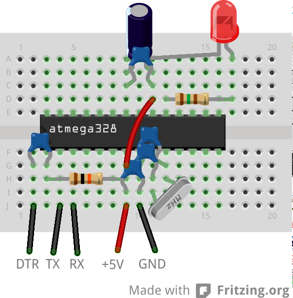
Now you can try uploading sketches to the ATMEGA328.
Some final bits, you can connect the last 100nF capacitor from the AREF pin to ground to help smooth out the analogue reference if you plan to use the analogue to digital converter and you can add a switch between the reset pin and ground to allow you to reset the ATMEGA328 whenever you want without having to manually short it to ground.
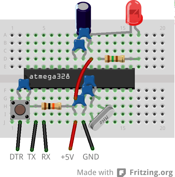
That's it! You now have a fully functional shrimp equivalent to the Arduino Uno. You should now try experimenting with the sketches, see if you can make the LED blink faster or slower, or even in a predetermined pattern (such as blinking out a message in Morse code). Then try connecting it up to other devices and circuits or build it into your own!